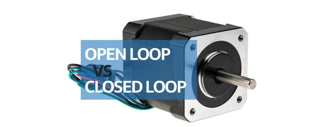
Open loop
One of the main advantages of stepper motors is their suitability for open-loop control. In open-loop control, the stepper motor is driven by a pulse sequence with a specific time interval, and feedback from sensors or corresponding electronic circuits is unnecessary in the control system. This type of circuit is simple and cost-effective, making open-loop control systems for stepper motors widely applicable in 3D printers, paper printers, CNC machines, and more.
However, stepper motors are often oversized to handle torque spikes, stalls, or other anomalies that could otherwise cause the motor to miss steps. Due to the nature of open-loop control, the system cannot recover from lost steps. When missed steps are critical to the application or process, an alternative solution is to operate the stepper motor in a closed-loop system, incorporating position feedback to detect and correct positioning errors. Although oversizing the motor with safety margins of 20-50% is a common practice, it results in wasted energy. Implementing closed-loop control can reduce this inefficiency.
Closed-loop control addresses issues such as resonance and step loss, enhancing performance and allowing stepper motors to achieve higher torque. In the case of Field-Oriented Control (FOC), it enables sensing of torque, speed, and position, effectively turning a stepper motor into a servo motor. Closed-loop control for stepper motors can be implemented using several techniques, which will be described below.
Servo Control / True Closed-Loop Control (FOC)
To maximize performance, a stepper motor can be treated as a 2-phase brushless servo motor, with the current regulated based on the error signal, similar to standard servo motors. This servo control method optimally delivers the required current for the move profile.

This ensures greater efficiency compared to alternative stepper control techniques. Enhanced efficiency translates into reduced heat generation and an extended motor lifespan.
Servo control mitigates the resonance issues often encountered with other control methods, enables high torque at low speeds, and allows the motor to utilize its full-rated torque without pullout torque limitations.
Compared to open-loop drives, closed-loop servo stepper drives offer significant performance advantages. Efficiency can increase by up to 6 times, and speed can increase by up to 4 times in closed-loop drives.
Stepper motors are similar to BLDC motors with a high pole count, which gives them high torque at lower speeds but also requires a fast control loop. Since stepper motors are rated for continuous current (in open-loop control, even when a stepper is idle, it still holds its position, wasting a lot of power), using FOC allows the motor to draw only as much current as necessary.
Just like in BLDC FOC control, you need to measure phase currents. This requires one current sensor per phase in the stepper motor. You can't use stock stepper driver ICs like the A4988 or TMC2209. Instead, you're limited to using either expensive ICs or building your power stage yourself with FETs and gate drivers. In summary, this approach is more costly, more complex, and much harder to implement, requiring you to write the FOC algorithm from scratch.
Unlike the servo/FOC method, there are other closed-loop methods that incorporate encoders for position correction but lack the additional features of true closed-loop control, leading to what can be called pseudo or not fully closed-loop modes. These modes are less efficient and cant produce same amount of torque like servo/FOC method.
Step Loss Compensation, or End Point Correction/Compensation
This method is the most prevalent form of closed-loop stepper control, and at the same time, it is the simplest and least efficient. In this method, the drive operates in microstepping mode while an encoder tracks the shaft position. If lost steps are detected, the controller commands additional steps to ensure the motor reaches the desired position. However, this system only compensates for missed steps at the end of a move, rather than continuously throughout the move profile.
Since the correction happens at the end of the move, and "moves" can be commanded at different rates, this mode is not truly real-time.
Continuous Error Compensation (Closed-Loop Microstepping)
Closed-loop microstepping continuously monitors the shaft or load position, generating an error signal. The controller adjusts commands in real-time throughout the entire move profile based on this signal. This method ensures that the stepper system, operating in microstepping mode, more accurately follows the move profile in real time, avoiding deviations during the move that would require a single compensation command at the end.
This mode has advantages in accuracy, but it is still power-inefficient and lacks the performance of a closed-loop stepper servo.

